Since main memory is usually too small to accommodate all the data and
programs permanently, the computer system must provide secondary
storage to back up main memory. Modern computer systems use disks
as the primary on-line storage medium for information (both programs
and data). The file system provides the mechanism for on-line storage
of and access to both data and programs residing on the disks. A file
is a collection of related information defined by its creator. The files are
mapped by the operating system onto physical devices. Files are normally
organized into directories for ease of use.
The devices that attach to a computer vary in many aspects. Some
devices transfer a character or a block of characters at a time. Some
can be accessed only sequentially, others randomly. Some transfer
data synchronously, others asynchronously. Some are dedicated, some
shared. They can be read-only or read–write. They vary greatly in speed.
In many ways, they are also the slowest major component of the
computer.
Because of all this device variation, the operating system needs to
provide a wide range of functionality to applications, to allow them to
control all aspects of the devices. One key goal of an operating system’s
I/O subsystem is to provide the simplest interface possible to the rest of
the system. Because devices are a performance bottleneck, another key
is to optimize I/O for maximum concurrency.Mass-Storage
Structure
The file system can be viewed logically as consisting of three parts. In Chapter
11, we examine the user and programmer interface to the file system. In
Chapter 12, we describe the internal data structures and algorithms used by
the operating system to implement this interface. In this chapter, we begin a
discussion of file systems at the lowest level: the structure of secondary storage.
We first describe the physical structure of magnetic disks and magnetic tapes.
We then describe disk-scheduling algorithms, which schedule the order of
disk I/Os to maximize performance. Next, we discuss disk formatting and
management of boot blocks, damaged blocks, and swap space. We conclude
with an examination of the structure of RAID systems.
CHAPTER OBJECTIVES
• To describe the physical structure of secondary storage devices and its
effects on the uses of the devices.
• To explain the performance characteristics of mass-storage devices.
• To evaluate disk scheduling algorithms.
• To discuss operating-system services provided for mass storage, including
RAID.
10.1 Overview of Mass-Storage Structure
In this section, we present a general overview of the physical structure of
secondary and tertiary storage devices.
10.1.1 Magnetic Disks
Magnetic disks provide the bulk of secondary storage for modern computer
systems. Conceptually, disks are relatively simple (Figure 10.1). Each disk
platter has a flat circular shape, like a CD. Common platter diameters range
from 1.8 to 3.5 inches. The two surfaces of a platter are covered with a magneticmaterial.We store information by recording it magnetically on the plattersA read–write head “flies” just above each surface of every platter. The
heads are attached to a disk arm that moves all the heads as a unit. The surface
of a platter is logically divided into circular tracks, which are subdivided into
sectors. The set of tracks that are at one arm position makes up a cylinder.
There may be thousands of concentric cylinders in a disk drive, and each track
may contain hundreds of sectors. The storage capacity of common disk drives
is measured in gigabytes.
When the disk is in use, a drive motor spins it at high speed. Most drives
rotate 60 to 250 times per second, specified in terms of rotations per minute
(RPM). Common drives spin at 5,400, 7,200, 10,000, and 15,000 RPM. Disk speed
has two parts. The transfer rate is the rate at which data flow between the drive
and the computer. The positioning time, or random-access time, consists of
two parts: the time necessary to move the disk arm to the desired cylinder,
called the seek time, and the time necessary for the desired sector to rotate to
the disk head, called the rotational latency. Typical disks can transfer several
megabytes of data per second, and they have seek times and rotational latencies
of several milliseconds.
Because the disk head flies on an extremely thin cushion of air (measured
in microns), there is a danger that the head will make contact with the disk
surface. Although the disk platters are coated with a thin protective layer, the
head will sometimes damage the magnetic surface. This accident is called a
head crash. A head crash normally cannot be repaired; the entire disk must be
replaced.
Adiskcanbe removable, allowing different disks to be mounted as needed.
Removable magnetic disks generally consist of one platter, held in a plastic
case to prevent damage while not in the disk drive. Other forms of removable
disks include CDs, DVDs, and Blu-ray discs as well as removable flash-memory
devices known as flash drives (which are a type of solid-state drive).A disk drive is attached to a computer by a set of wires called an I/O
bus. Several kinds of buses are available, including advanced technology
attachment (ATA), serial ATA (SATA), eSATA, universal serial bus (USB), and
fibre channel (FC). The data transfers on a bus are carried out by special
electronic processors called controllers. The host controller is the controller at
the computer end of the bus. A disk controller is built into each disk drive. To
perform a disk I/O operation, the computer places a command into the host
controller, typically using memory-mapped I/O ports, as described in Section
9.7.3. The host controller then sends the command via messages to the disk
controller, and the disk controller operates the disk-drive hardware to carry
out the command. Disk controllers usually have a built-in cache. Data transfer
at the disk drive happens between the cache and the disk surface, and data
transfer to the host, at fast electronic speeds, occurs between the cache and the
host controller.
10.1.2 Solid-State Disks
Sometimes old technologies are used in new ways as economics change or
the technologies evolve. An example is the growing importance of solid-state
disks, or SSDs. Simply described, an SSD is nonvolatile memory that is used like
a hard drive. There are many variations of this technology, from DRAM with a
battery to allow it to maintain its state in a power failure through flash-memory
technologies like single-level cell (SLC) and multilevel cell (MLC) chips.
SSDs have the same characteristics as traditional hard disks but can be more
reliable because they have no moving parts and faster because they have no
seek time or latency. In addition, they consume less power. However, they are
more expensive per megabyte than traditional hard disks, have less capacity
than the larger hard disks, and may have shorter life spans than hard disks,
so their uses are somewhat limited. One use for SSDs is in storage arrays,
where they hold file-system metadata that require high performance. SSDs are
also used in some laptop computers to make them smaller, faster, and more
energy-efficient.
Because SSDs can be much faster than magnetic disk drives, standard bus
interfaces can cause a major limit on throughput. Some SSDs are designed to
connect directly to the system bus (PCI, for example). SSDs are changing other
traditional aspects of computer design as well. Some systems use them as
a direct replacement for disk drives, while others use them as a new cache
tier, moving data between magnetic disks, SSDs, and memory to optimize
performance.
In the remainder of this chapter, some sections pertain to SSDs, while
others do not. For example, because SSDs have no disk head, disk-scheduling
algorithms largely do not apply. Throughput and formatting, however,
10.1.3 Magnetic Tapes
Magnetic tape was used as an early secondary-storage medium. Although it
is relatively permanent and can hold large quantities of data, its access time
is slow compared with that of main memory and magnetic disk. In addition,
random access to magnetic tape is about a thousand times slower than random
access to magnetic disk, so tapes are not very useful for secondary storage.Tapes are used mainly for backup, for storage of infrequently used information,
and as a medium for transferring information from one system to another.
A tape is kept in a spool and is wound or rewound past a read–write head.
Moving to the correct spot on a tape can take minutes, but once positioned, tape
drives can write data at speeds comparable to disk drives. Tape capacities vary
greatly, depending on the particular kind of tape drive, with current capacities
exceeding several terabytes. Some tapes have built-in compression that can
more than double the effective storage. Tapes and their drivers are usually
categorized by width, including 4, 8, and 19 millimeters and 1/4 and 1/2 inch.
Some are named according to technology, such as LTO-5 and SDLT.
10.2 Disk Structure
Modern magnetic disk drives are addressed as large one-dimensional arrays of
logical blocks, where the logical block is the smallest unit of transfer. The size
of a logical block is usually 512 bytes, although some disks can be low-level
formatted to have a different logical block size, such as 1,024 bytes. This option
is described in Section 10.5.1. The one-dimensional array of logical blocks is
mapped onto the sectors of the disk sequentially. Sector 0 is the first sector
of the first track on the outermost cylinder. The mapping proceeds in order
through that track, then through the rest of the tracks in that cylinder, and then
through the rest of the cylinders from outermost to innermost.
By using this mapping, we can—at least in theory—convert a logical block
number into an old-style disk address that consists of a cylinder number, a track
number within that cylinder, and a sector number within that track. In practice,
it is difficult to perform this translation, for two reasons. First, most disks have
some defective sectors, but the mapping hides this by substituting spare sectors
from elsewhere on the disk. Second, the number of sectors per track is not a
constant on some drives.
Let’s look more closely at the second reason. On media that use constant
linear velocity (CLV), the density of bits per track is uniform. The farther a
track is from the center of the disk, the greater its length, so the more sectors it
can hold. As we move from outer zones to inner zones, the number of sectors
per track decreases. Tracks in the outermost zone typically hold 40 percent
more sectors than do tracks in the innermost zone. The drive increases its
rotation speed as the head moves from the outer to the inner tracks to keep
the same rate of data moving under the head. This method is used in CD-ROM
and DVD-ROM drives. Alternatively, the disk rotation speed can stay constant;
in this case, the density of bits decreases from inner tracks to outer tracks to
keep the data rate constant. This method is used in hard disks and is known as
constant angular velocity (CAV).
The number of sectors per track has been increasing as disk technology
improves, and the outer zone of a disk usually has several hundred sectors per
track. Similarly, the number of cylinders per disk has been increasing; large
disks have tens of thousands of cylinders.
10.3 Disk Attachment
Computers access disk storage in two ways. One way is via I/O ports (or
host-attached storage); this is common on small systems. The other way is via
a remote host in a distributed file system; this is referred to as network-attached
storage.
10.3.1 Host-Attached Storage
Host-attached storage is storage accessed through local I/O ports. These ports
use several technologies. The typical desktop PC uses an I/O bus architecture
called IDE or ATA. This architecture supports a maximum of two drives per I/O
bus. A newer, similar protocol that has simplified cabling is SATA.
High-end workstations and servers generally use more sophisticated I/O
architectures such as fibre channel (FC), a high-speed serial architecture that
can operate over optical fiber or over a four-conductor copper cable. It has
two variants. One is a large switched fabric having a 24-bit address space. This
variant is expected to dominate in the future and is the basis of storage-area
networks (SANs), discussed in Section 10.3.3. Because of the large address space
and the switched nature of the communication, multiple hosts and storage
devices can attach to the fabric, allowing great flexibility in I/O communication.
The other FC variant is an arbitrated loop (FC-AL) that can address 126 devices
(drives and controllers).
A wide variety of storage devices are suitable for use as host-attached
storage. Among these are hard disk drives, RAID arrays, and CD, DVD, and
tape drives. The I/O commands that initiate data transfers to a host-attached
storage device are reads andwrites of logical data blocks directed to specifically
identified storage units (such as bus ID or target logical unit).
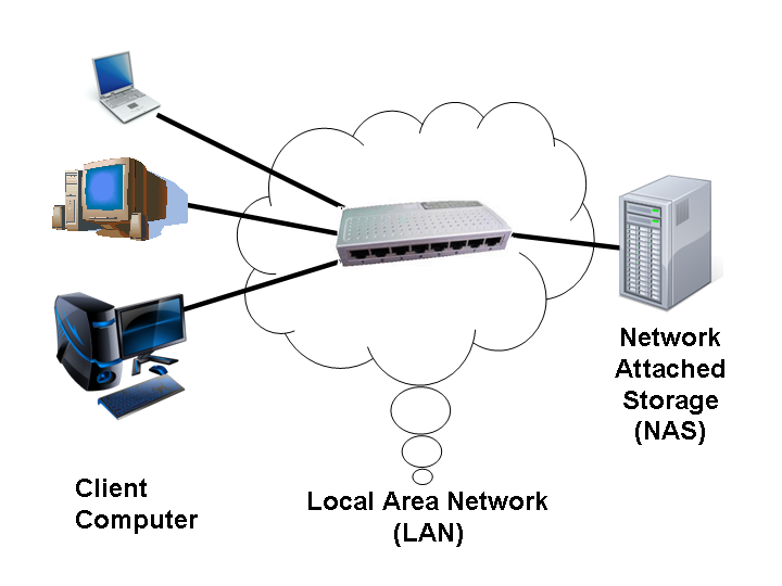
10.3.2 Network-Attached Storage
A network-attached storage (NAS) device is a special-purpose storage system
that is accessed remotely over a data network (Figure 10.2). Clients access
network-attached storage via a remote-procedure-call interface such as NFS
for UNIX systems or CIFS for Windows machines. The remote procedure calls
(RPCs) are carried via TCP or UDP over an IP network—usually the same localarea
network (LAN) that carries all data traffic to the clients. Thus, it may be
easiest to think of NAS as simply another storage-access protocol. The networkattached
storage unit is usually implemented as a RAID array with software
that implements the RPC interface.
 a LAN to share a pool of storage with the same ease of naming and access
enjoyed with local host-attached storage. However, it tends to be less efficient
and have lower performance than some direct-attached storage options.
iSCSI is the latest network-attached storage protocol. In essence, it uses the
IP network protocol to carry the SCSI protocol. Thus, networks—rather than
SCSI cables—can be used as the interconnects between hosts and their storage.
As a result, hosts can treat their storage as if it were directly attached, even if
the storage is distant from the host.
10.3.3 Storage-Area Network
One drawback of network-attached storage systems is that the storage I/O
operations consume bandwidth on the data network, thereby increasing the
latency of network communication. This problem can be particularly acute
in large client–server installations—the communication between servers and
clients competes for bandwidth with the communication among servers and
storage devices.
Astorage-area network (SAN) is a private network (using storage protocols
rather than networking protocols) connecting servers and storage units, as
shown in Figure 10.3. The power of a SAN lies in its flexibility. Multiple hosts
and multiple storage arrays can attach to the same SAN, and storage can
be dynamically allocated to hosts. A SAN switch allows or prohibits access
between the hosts and the storage. As one example, if a host is running low
on disk space, the SAN can be configured to allocate more storage to that host.
SANs make it possible for clusters of servers to share the same storage and for
storage arrays to include multiple direct host connections. SANs typically have
more ports—as well as more expensive ports—than storage arrays.
FC is the most common SAN interconnect, although the simplicity of iSCSI is
increasing its use. Another SAN interconnect is InfiniBand — a special-purpose
bus architecture that provides hardware and software support for high-speed
10.4 Disk Scheduling
One of the responsibilities of the operating system is to use the hardware
efficiently. For the disk drives, meeting this responsibility entails having fastaccess time and large disk bandwidth. For magnetic disks, the access time has
two major components, as mentioned in Section 10.1.1. The seek time is the
time for the disk arm to move the heads to the cylinder containing the desired
sector. The rotational latency is the additional time for the disk to rotate the
desired sector to the disk head. The disk bandwidth is the total number of bytes
transferred, divided by the total time between the first request for service and
the completion of the last transfer. We can improve both the access time and
the bandwidth by managing the order in which disk I/O requests are serviced.
Whenever a process needs I/O to or from the disk, it issues a system call to
the operating system. The request specifies several pieces of information:
• Whether this operation is input or output
• What the disk address for the transfer is
• What the memory address for the transfer is
• What the number of sectors to be transferred is
If the desired disk drive and controller are available, the request can be
serviced immediately. If the drive or controller is busy, any new requests
for service will be placed in the queue of pending requests for that drive.
For a multiprogramming system with many processes, the disk queue may
often have several pending requests. Thus, when one request is completed, the
operating system chooses which pending request to service next. How does
the operating system make this choice? Any one of several disk-scheduling
algorithms can be used, and we discuss them next.
ok just it explenation for me, se youu :)
Tidak ada komentar:
Posting Komentar